Pages

Showing posts with label Destruction. Show all posts

Thursday, January 16, 2014

Breaking Ego out of his prison

Hello. So I did this shot last year in June and I wanted to do a little write up about how I went about solving the shot.

In this shot we had Ego, a dragon, breaking out of it's prison. The main problem I faced with the shot was that I got the final animation of the dragon around a week before deadline and I just didn't have the time to refine the dust and debris and render them out. So, the output here has been achieved in a little over 3 days. In the end, we were not even able to render out the dust passes. Anyway, this is how I went about solving it.

The models were done by Ross Hildick. You can go and check out his blog here: http://rosshildick3d.wordpress.com/

This is the final result I was able to produce:

The final result

When I was handed the shot, the first thing I analysed was the structure of the building. After having a discussion with the director, we came to a conclusion that this building was an old castle sort of structure and didn't have any iron reinforcements inside. So the only material used was stone. This meant that I didn't need to worry about the bending and deformation of metal rods.

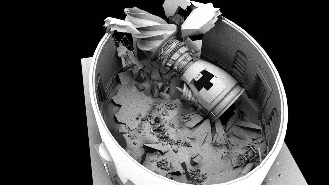
I looked at the animation of the dragon and I judged the force with which he was coming out. I then divided the upper part of the tower into different parts according to the amount of impact they would be receiving from the dragon's body. This can be seen in the image below:

Geometry broken down into collision groups

Here we can clearly see the parts I broke the geometry into. The red one is the main impact group which takes the direct hit from the dragon. These rocks would be completely broken. Next would be the secondary main impact group. These bricks received impact as well, but not direct impact. So, the fractured, but into bigger chunks. Moving further out is the secondary impact group. These rocks didn't receive direct impact but were unsettled by the impact to the neighboring rocks. So, they just fall off. Beyond this I made several other groups which would stay glued together but will form tumbling geometry.

I used the RBD solver for this because I wasn't really happy with the result the Bullet engine was giving me. After breaking these areas down, I imported the geometry into Houdini as separate groups. I then started working from inwards to outside. I fractured the main impact group first. After I was happy with the result. I wrote it out through a ROP output driver. In the next file when doing the next group I imported this first geometry as collision geometry and went ahead with solving the shot, working outwards constantly.

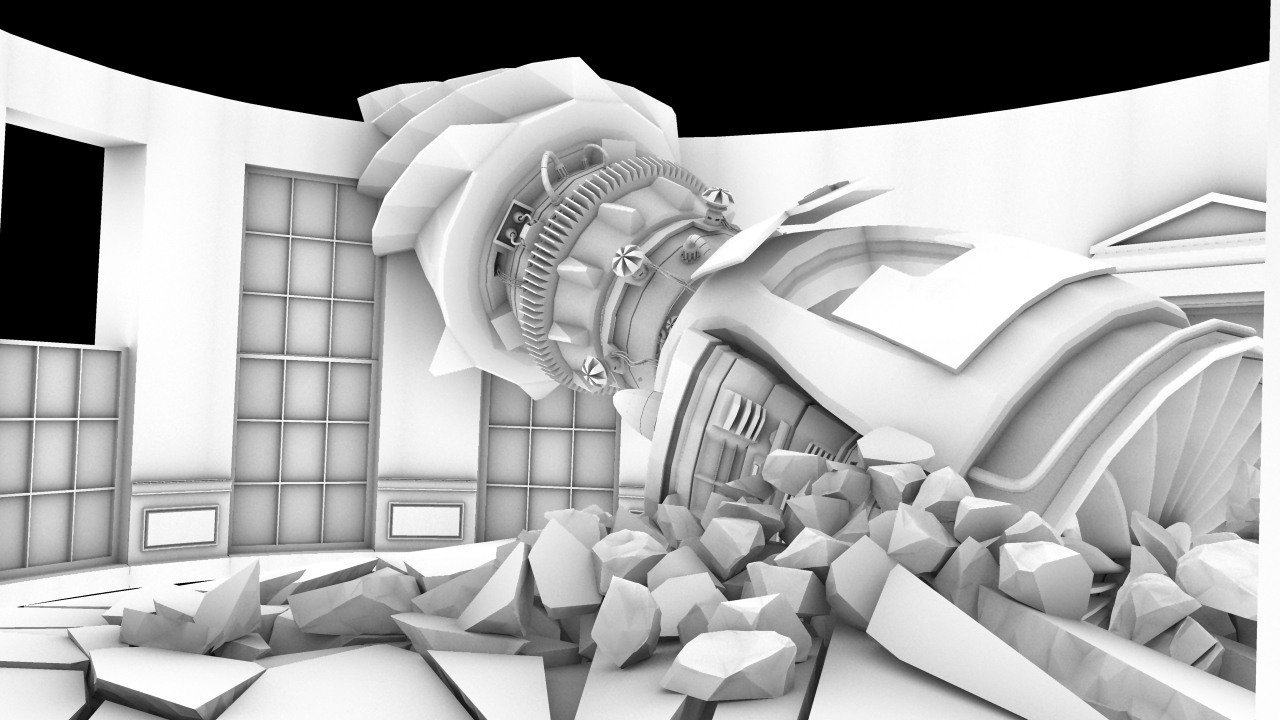
In the picture below you can see all the major groups:

Various collision groups

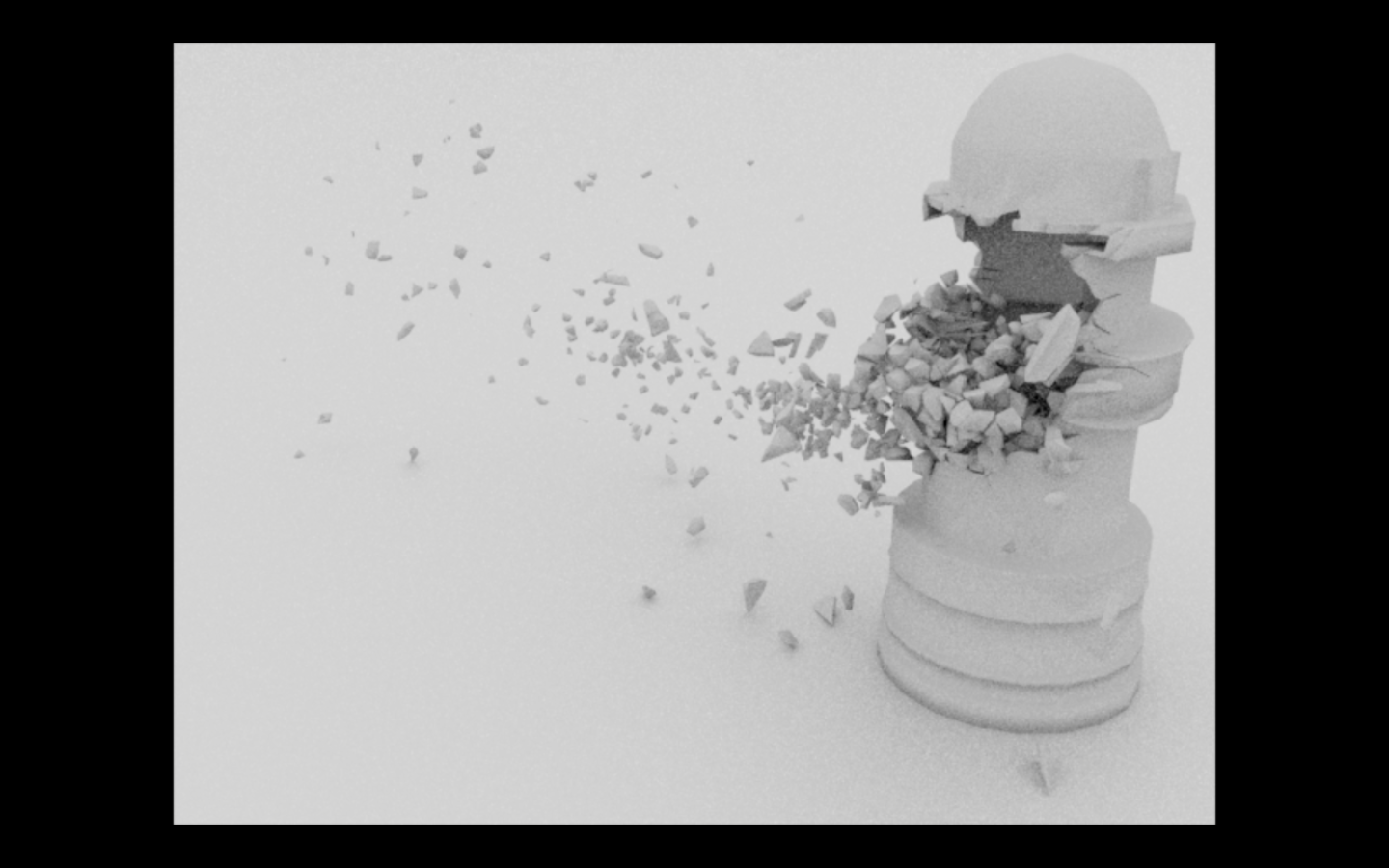
After this, ideally, I would have done a dust and debris solution, but due to the lack of time, I just added a simple smoke solution on top of this. After 3 passes of smoke was added and all the layers were brought together, this is how the final output looked like.

Smoke passes and final output

Below are some screenshots of the scene graphs:

The overall scene graph

The DOP network

SOP-network for one of the groups. This shows how I handled fracturing

So that was about it. It was a really simple fracture. I wouldn't say I am proud of it, but it is something. Feel free to message me if you want any clarification on this.

Happy fracturing!

Wednesday, February 6, 2013

Sony Games Modelling - 5

Putting everything together now. One more pass at set dressing and then I get into texturing this. Not really looking forward to it.

Work in progress

Sunday, February 3, 2013

Friday, January 18, 2013

Houdini Fracture Systems 4

So moving on from where I left off, I went on and used the concepts I have been learning in the past weeks and applied them to some dummy geo that Ross made for me. This is mainly a visual post, so no descriptions here and frankly this is very basic, I don't think I can add anything interesting to it :)

This is the final result I got from this:

Destruction and Debris: Rough test 

The process for this was the same as in the earlier blogposts.

Step 1: Preparing the geometry for destruction. Adding surface and interior detail, thickness and scaling for the scene.

Step 2: Painting the areas to be effected

Step 3: Scattering points using the voronoifracturepoints node

Adding fracture points and tweaking to get the desired look

 Step 4: Doing the Voronoi pre-fracturing

Voronoi pre-fracturing
The fractured geometry

Step 5: Adding a ground plane and fracturing using a collision object


I am happy with the result for this is the level of detail I am working at. This is basically a rough test for a upcoming rough test, so it is fine. There are still a lot of things to tweak but I would do that on the final dummy geometry with the final collision object.

That's all for now. Here is the link to the video of the simulation on Vimeo:


Friday, January 11, 2013

Houdini Fracture Systems 3

Tonight was a very slow night. Got stuck in several places and then had to do a lot of sims on Houdini and they can take a while.

I worked on pre-fracturing using geometry today. This is the result of the pre-fracturing:

Pre-fracturing using geometry

The node-network for the pre-fracturing

For this operation, I used a sphere and fractured it using a grid.

The Sphere with the intersecting grid use to fracture it
Voronoi fracturing applied
Visualising with the explodedview SOP
Visualising with noise
Adding some clustering to the internal pieces

After this I moved on to checking out some bullet simulations. Here is the output:

RBD with bricks
RBD with more random pieces
Adding some levels to the system and adding debris

It's morning now, so I need to go home, but just before going back I am testing out things I researched in the last couple of days, on the dummy geometry that needs to be fractured. This is a very rough test, and the geo still needs to be prepared for the fracture first.

The imported dummy geometry

Pre-fracturing using Voronoi

Will be working on it in the coming days. Let's see how that goes :)

Off for the weekend now.. Bbye labs! Forever!! Till Monday :p


Thursday, January 10, 2013

Houdini Fracture Systems 2

Day 2 of working with Houdini fracturing. Found a good basic tutorial for Voronoi fracturing. This approach combines the best of both worlds, pre-fracturing AND dynamic fracturing.

Pre-Visualising dynamic fracturing

This is the final output from the dynamic fracturing:

Final output of the dynamic fracture

Below is kind-of flip-book of the simulation. I am working on a Linux system, so can't really take screen-captures and can't be bothered to render out the sequence.


The basic problem I face when doing destruction is that I am faced with two choices. First is that I can pre-fracture stuff and just apply RBD on to the pieces and live happily ever after. However, the problem with the approach is that as I am painting the fracture or creating it procedurally, it either looks contrived or looks too uniform and artificial. The pro being that it is much faster and easier to control. Second option is doing a dynamic fracture. This is physically more accurate, so gives a better looking result. However, the problem with this approach is speed. Every time a parameter is changed, you need to re-run the sim and wait to see how the result looks like.

This approach that I found tonight is a good mid-way between the two. We get the pre-visualisation power from the pre-fracturing we do and the accuracy from the dynamic fracturing. It might not be a major invention and might just be a standard industry practice, but it is definitely very interesting for me :)

How this works is that we build a very simple network using SOPs. First of all we take the geometry we want to fracture. In this case it is a sphere, with a mountain SOP appended to it giving the look of a rock.

The pre-visualisation pre-fracturing network

The base geometry

Next, a scatter node is attached to it and 1 point is placed on the mesh. This gives us an impact point. This information, along with the base geometry is passed on to the voronoifracturepoints SOP. This SOP adds several parameters to the geometry passed down to it.

voronoifracturepoints SOP adding fracture points to the geo

The above picture is the output of the voronoifracturepoints SOP. The sphere represents the impact radius. The yellow points are the fracture points ON the surface, the red points represent the interior points and the blue points are the back-faces.

The output of this SOP is passed on to the voronoifracture SOP. Here we can visualise the fracturing.

Creating fractures using fracture points

Voronoi pre-fracturing

I then played with a few attributes till I got the look I was looking for. This was the result I got in the end. Notice that this has much more size variation than before. Now there are some small pieces which will form the fine debris that lends believability to the scene.

Tweaking the parameters to get the desired look

After visualising the exterior, I appended an explodedview SOP that helps visualising the interior geometry.

The GL view showing the interior after appending the explodedview SOP

The explodedview SOP is an important part of the visualisation process. Below are some results from the SOP.


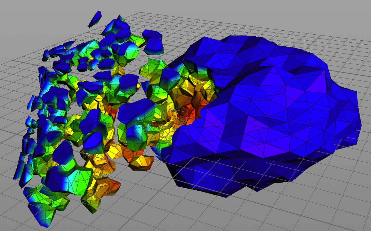
A thing to notice is that the main chunk of the rock is still intact. This is achieved by turning on 'clustering'. Once inside the fractured geo, I turned on 'add interior detail' and also the 'visualise noise scale' option. This gave me a visualisation of how the noise impacted the interior pieces. Red areas are maximum scale and blue areas are minimum scale.

Visualising the interior details using noise scale option

Once this pre-visualisation was done, I created a DOP net, simulated the rock falling and hitting the ground plane and made it breakable. Then I created relative references between the voronoifracture and voronoifracturepoints SOPs and fractureparms node in the DOP network.

By doing this, I got a result very close to my visualisation, but I still had the option to fracture dynamically and add steps, multiple fracturing etc.


Also, the relative references to the SOP level are good as if we need to change our result, we can go back to the SOPs, re-visualise and the DOP will update in a relatively controlled way.

Below are the snapshots from two scenarios for comparison. Notice that the pre-vis is very close to the dynamic fracture.

Pre Visualisation


The result of the dynamic fracturing

That was a LONG post, but I enjoyed explaining the process and hopefully someone will find ii useful if they are stuck with this stuff. It will definitely help me in a week, when I forget how I managed to do this :p

Here are some more pretty pictures. Enjoy :)